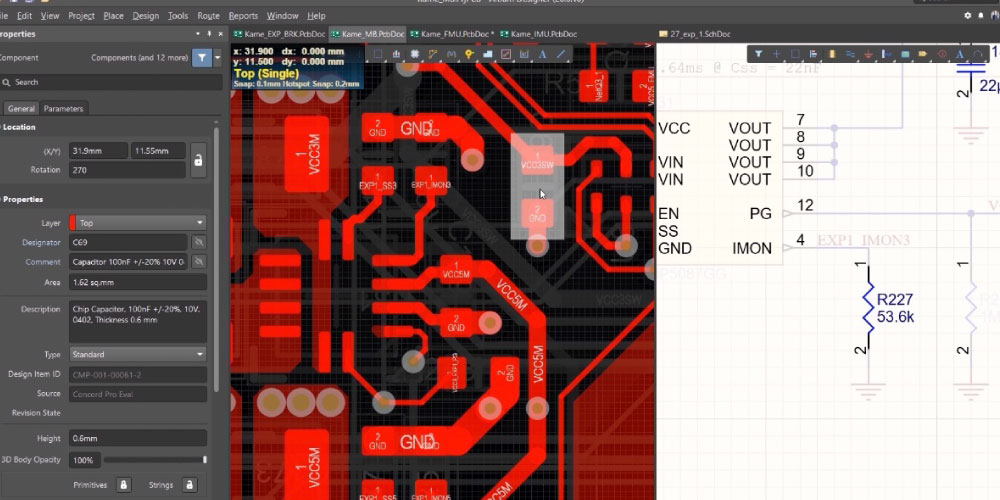
The BOM calls for one connector while the assembly drawing shows another. Purchasing needs an answer before ordering either part. PCB assembly documentation errors often arise at the boundaries between files, departments, and revisions.
The package must describe one buildable configuration that engineering, procurement, manufacturing, and test interpret consistently. A reconciliation review checks that agreement before a supplier must resolve conflicting instructions.
Find PCB assembly documentation errors between files
Create a release index identifying the assembly part number, applicable document revisions, and the date the package was issued. A schematic revision and an assembly revision may differ legitimately. What matters is whether the index explains which combination is approved.
Avoid a folder containing several plausible versions with filenames such as “final,” “final2,” and “latest.” Archive superseded material outside the release package. If a file is preliminary, label it clearly and identify the decisions still outstanding. Keep the original export and any approved corrections connected through a controlled release record.
Versa’s printed circuit assembly documentation guide lists the main manufacturing inputs. Use that list to check completeness, then examine how those inputs agree with one another. A complete set of inconsistent files is still an unreliable production package.
Reconcile the BOM with populated positions
Every component that will be installed needs an unambiguous identity. Check manufacturer part numbers, quantities, reference designators, and the approved package. Two components can share a nominal electrical value while differing in dimensions, ratings, tolerance, or behavior. A purchasing description is not a substitute for an approved part number.
Look specifically for positions that are not populated. The BOM and assembly documentation should distinguish deliberate omissions from missing data. If several product variants use one board, identify the populated and omitted positions for each configuration rather than leaving the assembler to infer them from a product name.
Approved alternatives also need boundaries. State whether an alternate is interchangeable for every variant or only a particular configuration. Keep unapproved candidate parts outside the released purchasing instructions until the responsible engineering team accepts them. A supplier finding an available substitute has not, by that action alone, changed the design authority’s requirements.
Verify orientation and mechanical fit
Placement data can describe a position and rotation without making every assembly requirement clear. Review polarity indicators, connector orientation, pin-one references, and the views used in drawings. A bottom-side view or mirrored image should be identified so it cannot be mistaken for a top-side view.
Mechanical information matters when an otherwise correct PCBA must fit an enclosure. Include board outline, mounting holes, height restrictions, and relevant mating features. Check the drawing against the actual connector selection. A revised component can alter clearance even when the electrical schematic remains unchanged.
Use a short annotated drawing to explain an unusual feature when a paragraph would leave room for interpretation. Keep that drawing under the same release control as the rest of the package. For the broader design context, refer to Versa’s article on design for manufacturing.
Avoid data exports without receiving requirements
Agree on the manufacturing data format before delivery. A successful CAD export proves that a file was created, not that it includes every input the recipient needs. Confirm fabrication layers, drill information, placement data, units, and the applicable software or exchange format.
The IPC-DPMX consortium describes standardized exchange of PCB design and manufacturing information. Such formats can support a consistent handoff, but acceptance and interpretation still depend on the manufacturer’s workflow. Verify the agreed export rather than assuming the format name resolves the whole transfer.
When moving between systems, compare a representative view or report with the source design. Check units and orientation explicitly. Do not edit an exported file informally to make it appear correct while leaving the originating design unchanged. That creates a new discrepancy at the next export.
Treat test and firmware files as production inputs
A board can be assembled to the drawing and still fail an undefined or outdated test. Include the applicable functional test procedure, limits, software, and fixture information. Identify which checks are mandatory for acceptance and which are engineering investigations.
Firmware should have a controlled identity and a verification step. Specify the image or configuration, the programming method, and the evidence expected after loading. Keep credentials and sensitive keys in an appropriate secure transfer process rather than embedding them in a general manufacturing folder.
If a revision changes electrical behavior, assess whether the test procedure changes too. A drawing update alone cannot ensure that an old test limit remains valid. Versa’s inspection, testing, and calibration services provide the relevant service context for discussing the required production checks.
The published manufacturing innovation case describes a medical-device customer approving Versa’s first article and then working with Versa on raw-material packaging, hand operations, and manufacturing efficiency. That experience supports a practical handoff rule: capture decisions made during the build in the next controlled package. The case does not establish that Versa approves an OEM’s medical device or replaces its product validation.
Close open questions through one record
Supplier questions often reveal an inconsistency before it becomes a build defect. Record the question, responsible owner, approved answer, affected documents, and closure date. Separate a clarification from a design change. A clarification explains an existing requirement; a design change alters it and may require a new release.
Avoid allowing an email attachment to become the only approved correction while the shared package remains outdated. Update the controlled files and tell all affected participants which package supersedes the old one. Purchasing should know whether a correction changes material already ordered. Production should know whether work already completed is affected.
Run a short reconciliation meeting
Before release, engineering can demonstrate one representative component, one mechanical interface, and one test requirement across the applicable files. Procurement checks purchasing identity and approved alternatives. Manufacturing checks assembly interpretation. Test confirms that acceptance criteria match the configuration.
Versa’s 2018 ISO 13485:2016 announcement reports that the transition required more record keeping as evidence of compliance, beyond written procedures. Bill Jackson, identified as Versa’s quality manager in that announcement, described that distinction. Apply it here by retaining resolved exceptions and approved answers, rather than a meeting attendance record alone. This historical account does not verify today’s certificate or staffing.
Make the next release easier to interpret
Maintain a compact checklist based on actual questions from previous builds. Add recurring errors, retire obsolete checks, and retain a record of what changed between releases. The goal is a package that remains understandable after the original designer moves to another project.
Documentation quality affects both manufacturing decisions and commercial assumptions. Download The Threat To OEM Success: Price and Lead Time for Versa’s ebook resource, then use a reconciled release package when discussing the next assembly quotation. Clear inputs give the conversation a firmer basis before material and production commitments are made.